Table of Contents
Introduction
DUALEM (DUAL-geometry ElectoMagnetic) geo-conductivity meters (GCMs) simultaneously measure terrain-conductivity to two distinct depths of exploration. DUALEM GCMs also detect shallowly buried conductors, giving diagnostic information about their depth and geometry.
This manual contains instructions for operating DUALEM Serial Number 0, in configurations with either 2-m (DUALEM-2) or 4-m (DUALEM-4) separation between its transmitter and receivers. This introductory section describes very briefly the theoretical basis of DUALEM. Subsequent sections provide details of equipment and maintenance, survey preparation, survey operation, and data processing. The manual concludes with technical specifications, a warranty statement and references.
DUALEM GCMs can be applied to many types of geological and environmental investigations. These include soil-salinity mapping, archaeology, the delineation of conductive contamination from salts and acids, and exploration for groundwater and clay. Electrically resistive targets at surface, such as aggregates, soil frost and tar pits, often are delineated successfully with GCMs. Buried resistors such as voids and complex features such as hydrocarbon contamination, if detectable at all, require meticulous technique and expert interpretation. Highly conductive bodies, such as steel drums, metal tanks and iron sulfides are readily detected by DUALEM. However, interpretation by a skilled geophysicist is required to determine the depth and shape of the feature.
Patented DUALEM instruments incorporate an EM-transmitter that operates at a fixed frequency and two EM-receivers, at a given horizontal separation from the transmitter, that are tuned to the frequency.

As shown in Figure 1, the transmitter and one of the receivers have horizontal windings, and these components form the horizontal co-planar geometry (HCP). The other receiver has vertical windings; it combines with the transmitter to form the perpendicular geometry (PRP).
DUALEM instruments are designed to operate within the low-frequency-approximation of EM response, as defined by Wait (1962). Low-induction-number (LIN) and resistive-limit are synonymous with low-frequency approximation. At LIN, an electromagnetic system has a stable depth-of-exploration (DOE), and response amplitudes are linearly proportional to conductivity.
The relative response of the earth at LIN follows from a simplification of Wait’s (ibid., 1982) analysis of response from a horizontally layered earth. For PRP the response, RiPRP, to an incremental layer in the earth is:
RiPRP = 2/(4s2 + 1)3/2
where s is the depth to the layer, in units of the transmitter-receiver separation.
Integrating with respect to s gives RcPRP, the cumulative response of the earth to the depth s:
RcPRP = 2s/(4s2 + 1)1/2
Corresponding formulae for HCP, adapted from those first published by McNeill (1980), are:
RiHCP = 4s/(4s2 + 1)3/2
where RiHCP is the response to an incremental layer at a depth of s separations, and:
RcHCP = 1 – 1/(4s2 + 1)1/2
where RcHCP is the cumulative response of the earth to depth s.
The cumulative responses of PRP and HCP are plotted in figure 2. The cumulative responses may be used as guides to DOE, in that they indicate the depths beyond which PRP and HCP are relatively insensitive to response from the earth. Response for PRP accumulates rapidly to a depth of about 0.6 transmitter-receiver separations, beyond which there is little sensitivity.
Thus, 0.6 separations is a reasonable value for the DOE of PRP. Although the change in cumulative response for HCP is less abrupt, McNeill (ibid.) proposed 1.5 separations as the DOE for HCP, and this value has become generally accepted.
In the DUALEM-4 configuration, the DOE of PRP is about 2.5 m, and the DOE of HCP is about 6 m.
When DUALEM is carried at a given height above the ground-surface, the DOE in the earth for each system is reduced by this height. For a typical operator, carrying the DUALEM at hip-height reduces each DOE in the earth by about 0.9 m.
As conductivity increases, DOE and the accuracy of conductivity measurements decrease, and interpretation becomes complex.
Figure 3 compares the true conductivity of a homogeneous earth to the apparent conductivities that will register on a DUALEM-4 on the surface of the earth.
Up to about 400 mS/m, PRP measurements remain fairly accurate; at this conductivity, DOE shrinks by about 10 %.
Thus, for measured conductivities up to 400 mS/m over a homogeneous or layered earth, the PRP geometry operates at LIN, with accurate measurement of conductivity to a known DOE.
The LIN range of HCP is much smaller. The 10% tolerance on conductivity underestimation and DOE shrinkage occurs at a measured conductivity of about 40 mS/m. At measured conductivities greater than this, sophisticated techniques (using in-phase and quadrature measurements from both PRP and HCP) are recommended for the interpretation of layering in the earth.
The LIN limit is inversely proportional to the square of the coil separation. Thus, with about one-half the coil separation, the DUALEM-2 PRP measurements remain accurate to about 1,600 mS/m, and the DUALEM-2 HCP measurements remain accurate to about 160 mS/m. Conductivities of geological materials are typically much lower than these values, with the exceptions of some sulfides, graphite and brine.
Where buried metal or similar heterogeneous features cause DUALEM to operate beyond the LIN range, DUALEM continues to produce accurate and useful measurements, but the interpretation of the results becomes complex.
Conductivity (i.e. quadrature) responds especially well to elongated conductors, such as metal pipes.
In-phase measurements become strong over highly conductive material, and are particularly effective for locating confined conductors, such as metal drums, or boulders of graphite or sulfide.
Figure 4 shows profiles of HCP in-phase and PRP in-phase that were measured by the DUALEM-2 at 1 m and 2 m from the top of an upright 200-L (55-gallon) steel drum, and figure 5 shows DUALEM-4 in-phase at 0.5 m, 1.75 m and 4 m from the top of the drum.
The DUALEM was aligned with the profile direction, with the receivers ahead of the transmitter. The designated measurement point is the centre of the instrument.
Note that the distances quoted in the figures extend from the top of the drum to the instrument. For comparison with survey results, the depth of burial of the drum is the quoted distance minus the carrying height of the instrument.
The shapes of the HCP and PRP profiles are distinct. The amplitude of the profiles decreases exponentially as the distance increases between the instrument and the drum, which limits the detection distance to about 2 m for the DUALEM-2 and about 3 m for the DUALEM-4.
Equipment and Maintenance
DUALEM is a scientific instrument that incorporates precise mechanical and electronic components. Reasonable care will allow the instrument to provide years of service. The user should be familiar with the equipment and its maintenance before surveying with the instrument.
Five booms are visible upon opening the lid of the shipping case. The short booms contain the DUALEM-2 transmitter and receiver. The longest booms contain the DUALEM-4 transmitter and receiver. The fifth boom, or core, contains the data processor and battery compartment. Clasps for fixing the transmitter and receiver to the core are visible on the bolsters near the ends of the core. The threaded socket for connecting the controller- or data-cable to the core is near one of the bolsters. The cables are partially visible beneath the booms, along with the harness for carrying the instrument.
The controller sits in the padding beneath the booms, along with 8 C-cell batteries. (A removable piece of padding covers the batteries.) Other items include a software/documentation disk and the user manual. Optional items are an external battery, power cable, and personal computer (PC).
Batteries
Rechargeable or non-rechargeable batteries may be used in the instrument. Batteries should be clean and dry. Battery contacts should be cleaned if necessary, with a cloth, emery cloth, very-fine sandpaper, etc. Similar care should be given the contacts of the battery holder.
To install batteries, loosen the thumb screw on the bottom of the core and remove the cover of the battery compartment. A fabric sleeve with a Velcro edge is taped to the bottom of the compartment. Lay the batteries in the sleeve, with their negative terminals oriented toward the hemispherical contacts, and their positive terminals oriented toward the removable, spring loaded contacts. Ensure that there are no gaps between the batteries. Close the sleeve, replace the cover and tighten the thumb screw.
If no use of the instrument is planned for an extended period, batteries should be removed to eliminate the possibility of depletion and corrosion. The instrument has an internal battery that maintains information in the instrument when there are no batteries in the battery compartment.
Boom
The 3-piece boom, which holds the transmitter and receivers of the instrument in their fixed arrangement, is made to exacting specifications from a fiber/resin composite. The composite has excellent stability to minimize drift and noise. The design and strength of the composite allows the boom to be both light and durable. Nevertheless, the boom should not be subjected to shocks and stresses greater than those encountered routinely in use and shipment.
Boom-pieces are fitted with clasps that fix the pieces mechanically and connectors that join the pieces electrically. The clasps should be kept clean, and the electrical connectors should be kept dry. Lubrication of the connectors is not recommended.
Cables
Cables supplied with the DUALEM, with their specialized connectors, are designed to function under all reasonable survey conditions. However, at several years, the typical service-life of the cables is less than that of the instrument. The following suggestions may help to extend cable serviceability.
In temperatures progressively below freezing, increasing care should be taken when flexing or coiling cables. At any temperature, crushing, shearing, twisting and straining the cable should be avoided, especially at the connectors. Connectors should be kept clean and dry. Cables should not be stored in strong sunlight or at high temperatures.
Controller
The controller combines a display, keypad, and cable with connector. The display shows the menu prompts of the software installed in the instrument. The user controls the function of the instrument using the keypad.
The display is of the liquid-crystal diode (LCD) type used on many consumer-products, and requires similar care. The display is protected by an acrylic window; dirt should be blown off, or wiped off with a clean, damp and soft cloth. Do not use harsh solvents, abrasive cleaners, or bend or hit the window.
The keys on the keypad record the response of the user to the menus and prompts. A response is registered when a key yields to gentle but firm momentary pressure. The keys are weatherproof, and should provide many years of flawless function if they are not pressed with excessive force, nor stored in a yield position.
In this manual, keypad keys marked with 1, 2, 3, and 4 are indicated by [1], [2], [3] and [4] respectively.
If you are operating in extreme temperature or in low light, you may not be able to see information on the display. If the display is too cold, nothing will appear; if the display is too hot, a 20-across-by-4–down array of dark rectangles will appear; in low light, the display is not readable.
To adjust the initial display, hold down [1] continuously while connecting the controller to the core and during the following procedures. As you connect the controller, you will hear a beep if the instrument is in serviceable condition. If there is reasonable ambient light, the words DISPLAY TEST will appear on the top line of the display.
If the display is unreadable due to low light, press [4] while holding down [1] and the display-light will come on. (Note that battery life shortens significantly if the instrument is operated with the display-light on.) You can turn off the light by disconnecting the controller, or by using a prompt in the DISPLAY CONTROL screen of INSTRUMENT SETUP.
If nothing appears on the display, press and hold [2] to increase contrast. If the contrast is too high, dark rectangles will appear around the characters on the display. To reduce contrast, press and hold [3] while you continue to hold down [1].
If the instrument is in its suspended state, with the controller attached, you can adjust the display by pressing and holding down [1] continuously during adjustment of contrast and/or display-light.
In unusual circumstances, * DISPLAY RESTART * may appear if power to the controller has been interrupted. If this message remains on the display for more than a few seconds, press [4], wait for the message ** SHUTTING DOWN ** to disappear from the display, and then press any key to restart the instrument.
Processor, Receivers and Transmitter
The processor, receivers and transmitter, located near the center and each end of the DUALEM, contain sophisticated electronic components. They are housed within the boom for protection against most hazards. The general recommendations for care apply to these parts; in particular, they should not be exposed to high-energy radiation.
Description follows of the structure of data in memory, the (initial) root menu of the controller, how to use the controller to read the battery voltage and the amount of free memory, and how to set the date and time.
Memory and Data Structure
The processor requires routine maintenance of its memory. The gross memory capacity of the processor is 1 megabyte (Mb), which provides space for about 50,000 records of measurements. Instruments are shipped from Dualem with this memory essentially clear for the acquisition of survey data.
After surveying, the contents of the memory should be transferred promptly to a PC, and the memory cleared for the acquisition of new data. Following this practice virtually ensures that there will always be ample space in memory for new data, reviewing data in memory will be faster and less prone to error, and the potential for the loss of survey data will be minimized.
Records are added sequentially to the memory. While proper usage should prevent this occurrence, records will be overwritten sequentially from the start of memory if the memory is full.
Root Menu
To use the processor, ensure that the processor has battery power. Attach the cable of the controller to the connector on the core. If the core is serviceable, the controller will emit a two-toned beep. If nothing appears on the display of the controller, wait 5 seconds after the last beep, press [4], wait 5 seconds, and then press and hold [1] to adjust the display as described in the Controller section.
If the controller emits a 3-toned beep, and * DISPLAY RESTART * appears on the first line of the display, press [4], wait for the message ** SHUTTING DOWN ** to disappear from the display, and then press any key.
Under normal circumstances, the words DISPLAY TEST will appear momentarily on the top line of the display, followed by a momentary display of information about the state of the instrument.
Following the introductory information, the ROOT menu of the processor will appear, as shown. The ROOT menu provides access to functions related to survey data, survey setup, and instrument setup. SUSPEND suspends the operation of the instrument.
From the ROOT menu, press [3] for instrument setup. The BATTERY/MEMORY screen will appear. vv.v represents the battery voltage in use by the instrument. rrrrr represents the number of records that currently contain no survey data. s represents the sign of the temperature, tt, inside the instrument.

To set the date and time, press [2] to view the DATE/TIME screen. yy-mo-dd represents the year, month and day, and hh:mm:ss represent the hour, minute and second. To make changes, press [3]. Otherwise, press [4] to return to the ROOT menu.

If you press [3], the SET DATE/TIME screen will appear, with a cursor under the year (yy) field. Press [1] and/or [2] to change the value of the field, or press [3] to save its value and move to the next field. When the values in the fields are correct, press [4] and the DATE/TIME screen will reappear. Then, press [4] to return to the ROOT menu, and press [4] once more to suspend the processor.
Survey Preparation
Before surveying, the target and situation of the survey should be considered when planning the mode of operation and sampling density. This section concludes with some notes on preparing the instrument for shipment to the survey site, including checks on battery voltage and available memory.
Survey Planning
A DUALEM survey typically has several goals. Three goals that are common to many surveys are the mapping of soils and bedrock, the detection of buried features, and the delineation of contamination in soils and groundwater.
Many surveyors find it beneficial to plan a survey that should be effective for the most difficult of the goals. The detail and precision that address the most difficult targets usually make the survey more than adequate for the other goals.
Targets become more difficult with increasing depth of burial, and decreasing size and conductivity-contrast. Detail and precision are governed by measurement density, the geometry of the instrument and the speed of surveying.
As discussed in the introduction, the DUALEM-2 has sensitivity to earth-layers to a depth of about 3 m, and to 200-L metal drums to a depth of about 2 m. Corresponding depths for the DUALEM-4 are about 6 m and 3 m. Smaller metal objects will be detectable only at lesser depths, and at smaller lateral offsets. Accordingly, if a goal of the survey is to detect metal objects of modest size, these objects represent the most difficult target.
The ultimate in survey detail and precision would entail an orthogonal grid of survey lines, with line spacing of about 1 m. The instrument would be aligned with the survey line, and would be positioned barely above ground level. The survey speed would be about 0.1 m/s.
In practice, detailed and precise surveys incorporate a set of parallel survey lines spaced at 2- to 5-m intervals, plus two orthogonal lines near opposite survey boundaries. The instrument is aligned with the survey line, and carried at hip-height. The survey is conducted at a walking speed of 0.5- to 1-m/s.
Where the most difficult target is substantially larger in area, such as a zone of contamination or a deposit of aggregate, the line spacing may be expanded such that 3 lines can be expected to cross a feature of interest. If the target is near the DOE, or has a subtle conductivity-contrast, the ground clearance of the instrument should be uniform and no greater than hip-height; the survey should be conducted at walking speed. Otherwise, the instrument may be suitably mounted on a vehicle or towed on a trailer, and the survey speed may be several metres-per-second.
If the survey area allows a choice of line direction, the survey lines should be laid out perpendicularly to the evident-or-assumed trend of the feature of interest. Intermediate, orthogonal or oblique lines frequently supplement the survey grid. For example, if buried metal or other waste is a target of the survey, supplementary lines may be laid out over ground that appears to have been disturbed.
The positional guidance required by the surveyor is related to the line spacing of the survey. The guidance should enable the surveyor to maintain actual line spacing within about 25% of the ideal spacing. Surveyors have used local guidance systems, and the time-stamp of DUALEM measurements can provide synchronization with global positioning systems.
Survey areas and local interference often make automatic positioning systems impractical. A general technique for guidance consists of establishing a grid of wood or plastic markers. Markers positioned at intervals of up to 20 m along every fourth survey line are usually sufficient.
The line-and-station system used by many surveyors is illustrated in figure 6. An origin is defined for the system, through which survey line zero passes. Station zero on line zero coincides with the origin.
A baseline, perpendicular to the set of survey lines, also intersects the origin. The direction of the baseline is defined as north if it is more closely aligned with geographic north-south than with east-west. Otherwise the direction is defined as east, which is the case in figure 5.
The distance along the baseline from the origin to a survey line gives the number of the survey line. The baseline direction is added to the survey line number to indicate the position of the survey line relative to the origin, according to the grid system.
If the baseline direction is north, then the survey line direction is east, and vice versa. In this example, the baseline direction is east, so the survey line direction is north.
The distance along a survey line from the baseline to a station gives the number of the station. The survey line direction is added to the station number to indicate the position of the station relative to the origin, according to the grid system.
Instrument Preparation
Before transporting the instrument to the survey site, open the lid of the shipping case, and verify that the boom-pieces, the controller, and the harness are inside. An external 12-V battery, PC, and data- and power-cables are optional. Instrument- and user-information, especially available memory and battery voltage, should be checked before securing the lid.
Instrument Setup
Instrument information and settings are viewed and set by choosing the INSTRUMENT SETUP selection on the ROOT menu. Instrument settings are selected by the user from fixed choices to govern the operation of the instrument. To view information and to make settings, connect the controller and display the ROOT menu of the processor.
(Some users operate the instrument using a PC in the place of the controller. This is done through a standard PC terminal program, with settings as described in the Data Transfer section.)

From the ROOT menu, press [3]. The BATTERY/MEMORY screen will appear. If the voltage is below 8 V, the batteries are nearing exhaustion. If there is insufficient memory to store the data to be acquired, data in memory should be erased, as described in DATA TRANSFER. The menu on the bottom line indicates that you can press [4] to return to the ROOT menu, [1] to cycle through the instrument setup screens in reverse alphabetical order, and [2] to cycle in forward alphabetical order, as follows:

The DATE/TIME screen was introduced previously, with instructions for setting the date and time. Press [2] for the next item, which is DISPLAY CONTROL.
The DISPLAY CONTROL screen allows the user to set the contrast level of the display, and control the display light. Note that operating with the light on will decrease battery endurance significantly. If you select [3], the following screen, with control settings, appears.
Press [1] to decrease the contrast of the display, and [2] to increase it. Press [3] to switch the display light on or off. (To ensure that you can always read the display, these controls are available while powering on, as described in the Controller section.) Press [4] to return to the initial DISPLAY CONTROL screen, and [2] for the next item.

MEASUREMENT PERIOD sets both the time between the recording of successive measurements, and the integration interval for each measurement. The instrument senses continuously the response of the earth to the transmitted field, and integrates the response into values that can be recorded.
If you set the measurement period (pppppppppp) to MANUAL, measurements will be recorded only when you trigger them. The integration interval for manually triggered measurements is the shortest available, which is about 0.8 seconds.
If you set the measurement period MANUAL/MULTIPLE, each time you trigger acquisition, the instrument will record the number of measurements you specified in REPEATS PER STATION, which is the next screen in INSTRUMENT SETUP. The integration interval for each measurement is the shortest available.
The other MEASUREMENT PERIOD settings are for automatic triggering. Settings for automatic triggering with the shortest integration interval are 1/2 SECOND for a measurement each half-second, 1 SECOND for 1 measurement per second, 2 SECONDS SHORT for 1 measurement every 2 seconds, 5 SECONDS SHORT for 1 measurement every 5 seconds, and 10 SECONDS SHORT for 1 measurement every 10 seconds.
For some automatic triggering settings, the integration interval can be the full measurement period. These settings are 2 SECONDS FULL, 5 SECONDS FULL and 10 SECONDS FULL.
The survey targets and techniques indicate which MEASUREMENT PERIOD setting to use. If stations have been established for the precise location of measurements, the MANUAL setting is appropriate. The settings for automatic triggering enable surveys to be conducted quickly and conveniently, although with less positional precision. If you plan to use automatic triggering, the survey target should be broad enough so that its response should be reasonably constant over the distance traversed during the measurement period. In other words, shorter periods should be used with smaller targets and faster survey speeds.
For a typical situation, where buried drums and conductive halos are surveyed at walking speed, the 1 SECOND setting is generally used. In conditions of low signal (e.g. over coarse, dry soil) or high noise (e.g. near power-lines), surveying slowly, with the integration interval equal to the full measurement period, will improve the quality of the data.

REPEATS PER STATION sets the number (r) of measurements that the instrument will record before changing the station number. The value can be any integer between 1 and 9. A setting of 1 is typical; a higher setting is used for manually triggered measurements in noisy conditions, or at various heights and/or orientations per station.

If the instrument is inactive, it will automatically suspend its operation after the length of time set by SLEEP DELAY. The settings are 5 MINUTES, 15 MINUTES, 30 MINUTES, 1 HOUR and 2 HOURS. The sleep countdown restarts with each keypress or measurement. Pressing [4] SUSPEND from the ROOT menu overrides the countdown, and suspends operation immediately.
With due consideration for the remaining battery life, you should set SLEEP DELAY so that the instrument will remain operating throughout breaks in surveying. Continuous operation will minimize a system drift that may occur, especially in cold conditions.

START MODE determines how the instrument will behave the next time it is turned on. Settings are DATA and ROOT MENU. With the ROOT MENU setting, the instrument will display the ROOT menu. With the DATA setting, the instrument goes directly to data acquisition. If, prior to shutting down, one of the automatic settings was selected for measurement period, the instrument will automatically start acquiring data according to that setting, until a [4] is pressed.

STATION FLIP determines whether the station increment will be reversed on successive survey lines. Settings are FLIP, which will reverse the increment, and NOFLIP, which will not. FLIP is a convenient choice for surveys in which successive lines are traversed in the opposite direction.
Survey Setup
Survey settings contain the initial information for the survey. To view and edit the survey settings, connect the controller and press [2] from the ROOT menu of the processor. The COMMENT screen will appear, as it is alphabetically the first in the series of survey settings.

COMMENT displays the number (nn) and contents (cccccccccccccccc) of the current comment. Thirty-two comments are stored in the processor; each comment contains up to 16 alphanumeric characters. A comment record can be appended to the records of survey data for purposes such as naming the operator, describing weather conditions, and noting the occurrence of features in the survey area. Press [2] to cycle through the series of survey settings, as follows:

LINE sets the number (snnnnn) of the current survey line. The line number can have any integer or zero value between –30000 and 30000.

LINE INCREMENT sets the increment (siiii) that will be added to the number of the current line to give the number for the next line. The increment can have any integer value between –3000 and 3000, but usually it indicates the distance between lines.

LINE POSITION sets a label (p) to indicate the position of lines on the survey grid relative to the survey origin. The label is appended to the line number. The label is usually N or E, but it can be a different alphanumeric character or blank.

STATION sets the number (snnnnn) of the current station on the current line. The station number can have any integer or zero value between –30000 and 30000.

STATION INCREMENT sets the increment (siiii) that is added to the current station number to give the next station number on a survey line. The increment can have any integer value from –3000 to 3000. ffffff shows flip status. The increment usually indicates time for automatic triggering, or distance for manual triggering.

STATION POSITION sets a label (p) to indicate the position of stations on the survey grid relative to the baseline. The label is appended to the station number. The label is usually N or E, but can be any alphanumeric character or blank.

SURVEY NAME sets the name (ssssssss) of the survey, which can contain up to 8 alphanumeric characters. An edited name will be written to a header record, to indicate the survey in which data on subsequent records were acquired. The current date is written to the header record as well.
Example of Survey Setup and Instrument Setup
This example prepares the instrument for a survey in an area with hummocks of ground and occasional scrap visible at surface. To follow the example, connect the controller to the processing boom and display the ROOT menu.

Press [2] to select SURVEY SETUP. The COMMENT screen will appear. Press [3] to display the COMMENT LIST screen. If no comments have been stored, the screen will appear as shown, with the 1: indicating the current position in the list. From this screen, you can press [1] to view the previous comment in the list, [2] to view the next comment in the list, [3] to edit the current comment, or [4] to make the displayed comment the current one, and return to the COMMENT screen.

Press [3] to display the COMMENT EDIT screen. Then press [1] and [2] to select the characters and press [3] to move the cursor to spell FLAG; this comment could be applied to measurements made over visible features such as hummocks, scrap, and the edges of distinct portions of the survey area. When complete, the display should look similar to the illustration. Press [4] to save the comment and return to COMMENT LIST, and [4] again to return to COMMENT in the series of survey settings.

Press [2] to cycle to the LINE screen, and then [3] to display the LINE EDIT screen. Use [1] and [2] to set the number of the line. ([3] cancels any change and restores the LINE screen.) In this example, the first line of the survey intersects the origin of the grid so its line number equals zero. Press [4] to save the value and return to the LINE screen.

Press [2] to cycle to the LINE INCREMENT screen, and then [3] to display the LINE INCREMENT EDIT screen. Use [1] and [2] to set the value of the line increment. ([3] cancels any change and restores the LINE INCREMENT screen.) In this example, the survey grid consists of lines oriented north-south, spaced at an interval of 5 m, so the line increment equals 5. Press [4] to save the value and return to the LINE INCREMENT screen.

Press [2] to cycle to the LINE POSITION screen, and then [3] to display the LINE POSITION EDIT screen. Use [1] and [2] to set the value of the position. ([3] cancels any change and restores the LINE POSITION screen. In this example, the survey lines lie successively to the east of the first line, so the value is E. Press [4] to save the position and return to the LINE POSITION screen.

Press [2] to cycle to the STATION screen, and then [3] to display the STATION EDIT screen. Use [1] and [2] to set the station number. ([3] cancels any change and restores the STATION screen.) In this example, the first station on the first line of the survey lies at the origin of the grid, so its station number is zero. Press [4] to save the value and return to the STATION screen.

Press [2] to cycle to the STATION INCREMENT screen, and then [3] to display the STN INCREMENT EDIT screen. Use [1] and [2] to set the station increment. ([3] cancels any change and restores the STATION INCREMENT screen.) In this example, measurements will be triggered automatically at a rate of once per second, so the increment is 1. Press [4] to save the value and return to the STATION INCREMENT screen.

Press [2] to cycle to the STATION POSITION screen, and then [3] to display the STN POSITION EDIT screen. Use [1] and [2] to set the station position. ([3] cancels any change and restores the STATION POSITION screen. In this example, the stations on the first line lie successively to the north of the origin, so the value is N. Press [4] to save the position and return to the STATION POSITION screen.

Press [2] to cycle to the SURVEY NAME screen, and then [3] to display the SURVEY NAME EDIT screen. [1] and [2] change characters and [3] moves the cursor. In this example, the name of the survey is BFIELD. Press [4] to write the name to a header record and to return to the SURVEY NAME screen. Press [4] to return to the ROOT menu, and then [3] to select INSTRUMENT SETUP.

Cycle through the screens for BATTERY/MEMORY, DATE/TIME and DISPLAY CONTROL by pressing [2] until MEASUREMENT PERIOD appears. In this example, measurements will be made automatically at 1 second intervals so, as may be necessary, press [3] to make the setting 1 SECOND. Press [2] to save this setting.

The display will cycle to the REPEATS PER STATION screen. In this example, one measurement will be taken with each station number so, as may be necessary, press [3] to make the setting 1. Press [2] to save the setting.

The display will cycle to the SLEEP DELAY screen. In this example, we want the instrument to “stay warm” through all breaks in the survey day so, as may be necessary, press [3] to make the setting 1 HOUR. Press [2] to save this setting.

The display will cycle to the START MODE screen. In this example, we want the instrument to display the root menu the next time it is turned on so, as may be necessary, press [3] to make the setting ROOT MENU. Press [2] to save this setting.

The display will cycle to the STATION FLIP screen. In this example, each subsequent line will be traversed in the opposite direction to the preceding line so, if necessary, press [3] to make the setting FLIP. Press [4] to save this setting and return to the ROOT menu.
A description follows of how “station flip” would function in this example. Line 0E will be surveyed first, and will take about 90 seconds to walk. Thus, the station number at the end of the line is expected to be about 90N. Line 5E will follow line 0E, and will be traversed in the opposite direction. With the FLIP setting, the starting station number for line 5E will be about 90N (i.e. the last station number on line 0E) and the station increment will be –1. If line 5E takes about 90 seconds to walk, the last station number on the line will be about 0N. This will be the starting station number for line 10E, and the increment will be +1, as it was for line 0E.
Surveying
Before surveying, the instrument must be assembled correctly. The method of traversing a survey area should be appropriate for the survey conditions. There are several options for data acquisition that optimize the quantity and quality of survey data; data can be reviewed during and following a survey.
Assembly
After arrival at the survey site, find a location away from any highly conductive objects or obvious sources of electrical interference. If the instrument has been suspended for at least 5 minutes or so, on startup it automatically performs internal tests to identify its current state, and strong external signals can interfere with this process.
Open the lid of the shipping case, and remove the components that you plan to use. Move the components away from the shipping case to avoid interference on startup.
All surveys require the core, a transmitter and a receiver. Surveys without external power require 8 C-cell batteries, which may be in the core, or beneath a section of foam in the shipping case. You normally use the harness to carry the instrument. You control the instrument with the controller, or with a PC and the data cable.
Join one of the transmitters to the end of the core nearest the data connector. The mating ends of these items are color-coded green. Join the corresponding receiver to the other end of the core. Lock the 3 pieces together using the steel hooks and clasps.
Four pieces make up the harness. Two of the pieces are slings, which loop and cinch around transmitter and the receiver. The free end of each sling is woven through a glide and D-ring. The other two pieces of the harness are padded shoulder straps. The clips at the ends of the shoulder straps connect to the D-rings of the slings. The connections and lengths of the pieces depend on your plan of traversing.
Survey Traversing
The manner of traversing the survey area should consider both the goals of the survey and the convenience and comfort of the user. Typically, an operator carries the instrument in manageable terrain and weather. The instrument can also be mounted on a vehicle or borne on a trailer. However, it should not be subjected to excessive vibration or stress. DUALEM instruments are not designed for airborne or marine surveying.
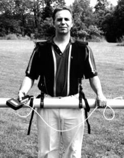
The height above the ground and the orientation of the instrument can be adjusted to suit the survey. Many surveys are conducted with the instrument at hip-height, and aligned with the orientation of the survey line. This orientation generates detailed and diagnostic profiles for the detection of buried metal; it should be used for surveys where this goal is important. At hip height, bumps against uneven ground or obstructions are less frequent.

To configure the harness for aligned surveying at hip height, loop one sling around the transmitter and the other around the receiver. Tighten the slings on the tubes next to the bolsters. Clip one end of each shoulder-strap into the D-ring for each sling. Adjust one shoulder-strap so that it is about 10 cm longer than the other strap. Place the straps over your shoulders, with the longer strap over the shoulder that is away from the side of your body on which the instrument will rest. As necessary, adjust the lengths of the slings (and straps) so that the instrument is suspended at hip height.
Sensitivity to changes in conductivity and to the presence of buried metal is best when measurements are taken just above the ground, and this survey height is practical over flat ground with low vegetation.
To configure the harness for aligned surveying at shin height, tighten the slings on the transmitter and receiver next to the bolsters. Ensure that the shoulder straps are equal in length and, as necessary, adjust the lengths of the slings (and straps) so that the instrument is suspended at shin height.
The alternate orientation is broadside, where the long axis of the instrument is perpendicular to the survey line. This orientation samples the conductivity laterally from the survey line better than the aligned orientation. The broadside orientation is practical for areas free of obstructions at the height of the instrument.
To configure the harness for broadside surveying, tighten the slings about the centre of the core at somewhat-less-than shoulder width. Clip both ends of one shoulder-strap into one D-ring, and both ends of the other strap into the other D-ring. Ensure the shoulder straps are equal in length and, as necessary, adjust the lengths of the slings (and straps) so that the instrument is suspended at hip height.
Aligned- and broadside-orientations can be combined to identify locations where there are significant and localized changes between measurements. Such changes indicate the presence of geometrically confined conductors, such as buried drums or fractures. Note that the PRP geometry is assymetrical, and consistent response requires consistent orientation of the instrument. For example, where surveying follows a serpentine path, the instrument should be readjusted as necessary to keep its geographical orientation constant.
Where fracture or other elongated features are the primary target of the survey, the azimuthal method is popular with some users. For the azimuthal method, measurements are made at each station with the boom aligned with a series of azimuths (e.g. 000, 045, 090, 135, 180, 225, 270, 315).
Survey Operation

Once survey setup and instrument setup are satisfactory, and the instrument has been assembled, survey operation can proceed. Ensure that batteries are installed, or that external power is available. Turn on the instrument by attaching the controller (or equivalent device) to the connector on the core. From the ROOT menu, press [1] and the SURVEY OPER screen will appear. The screen shows the survey name (ssssssss) that has been most recently recorded to memory, and date (yy-mo-dd) that the name was stored.
The coils of the instrument form the HCP and PRP geometries when the connector is vertical, i.e. on the top (or bottom) of the core. Note also that you can orient the coils in the vertical coplanar and null geometries by rotating the instrument so that the connector is on the side. Accordingly, some care should be taken during surveying to maintain the instrument in the planned orientation.
Data Acquisition
To acquire data, press [1] from the SURVEY OPER screen. The instrument will take measurements and display a screen in accordance with the setting of MEASUREMENT PERIOD. For the MANUAL setting, a single measurement will be taken; for the MANUAL/MULTIPLE setting, the instrument will take the number of measurements specified with REPEATS PER STATION.
With either setting, the instrument will display the 1:ACQ screen. The top line shows the key prompts. The second line shows the survey line number (slllll) and position (p), station number (tmmmmm) and position(q), and the number of the measurement (r) to be made next. The lower lines show HCP conductivity (uccc.c), HCP in-phase (viii.i), PRP conductivity (wddd.d) and PRP in-phase (xjjj.j) of the measurement most recently recorded.
For any other setting of MEASUREMENT PERIOD pressing [2] will initiate the automatic recording of measurements, at the interval specified by the setting, and the AUTO screen will appear. The station (tmmmmmq), measurement number (r) (if appropriate), HCP conductivity (uccc.c), HCP in-phase (viii.i), PRP conductivity (wddd.d) and PRP in-phase (xjjj.j) will update as recording continues. A record containing the current comment may be inserted into the ongoing measurement records by pressing [2]; the comment will be displayed momentarily. Pressing [3] increments the current line number (and flips the station increment if the STATION FLIP is FLIP). Pressing [4] stops the automatic recording, and restores the SURVEY OPER screen.

From the 1:ACQ screen, comment records can be appended to measurement records by pressing [2]. Subsequently, [1] displays the previous comment in the comment list, [2] displays the next comment in the list, [3] restores the 1:REC screen without recording the comment, and [4] restores the screen and records the comment.

Pressing [3] from the 1:ACQ screen repeats the last measurement sequence, re-using the same station- and/or measurement-number(s). Pressing [4] restores the SURVEY OPER screen.
Line/Station Adjustment

From the SURVEY OPER screen, press [2] and the LINE/STATION screen will appear. The screen shows the current line number (slllll), position (p), and increment (uiii), and station number (tmmmmm), position (q), and increment(vjjjj). Pressing [2] changes the line number by the line increment. This is done after completing a line and before starting the next line; it can be pressed several times if several survey lines are to be skipped. (If the station flip is set to FLIP, the station increment will be reversed for the next line that is surveyed, regardless of how many line numbers may be skipped.) Pressing [3] changes the station number by the station increment, in case stations are to be skipped. Press [1] to cancel the line/station adjustment if, for example, you have advanced the line or station number beyond the value you want. (If these numbers are incorrect, you can edit them through ROOT menu item 2:SURVEY SETUP.) Press [4] to store the adjustments. Pressing either [1] or [4] will restore the SURVEY OPER screen.
Data Review
After surveying, data can be reviewed to check for quality and completeness. To review records, press [3] from the SURVEY OPER screen.
The initial REVIEW RECORD screen shows information about the last record on which data have been written. The number of the record in the memory sequence is indicated by eeeee. If it is a measurement record, the number and position (sllllp) of the survey line, the number and position (tmmmmmq) of the station, the measurement number for the station (r), and the time (hh:mm:ss) stored on the record will be displayed.

With a measurement record, pressing [3] from the REVIEW RECORD screen displays the measurements of HCP conductivity (uccc.c), HCP in-phase (viii.i), PRP conductivity (wddd.d) and PRP in-phase (xjjj.j), in addition to the line (slllllp), station (tmmmmmq) and measurement number (r). Pressing [3] from this screen restores the REVIEW RECORD screen with the record number and time.
With any REVIEW RECORD screen, you can press [1] to view information on the previous record, [2] to view information on the next record, or [4] to return to the SURVEY OPER screen.

If the REVIEW RECORD screen is showing information from a header record, the record number (eeeee), the survey name (ssssssss) and the date (yy-mo-dd) appear.

If the REVIEW RECORD screen is showing information from a status record, the record number (eeeee), the internal temperature of the instrument (stt), and time (hh:mm:ss) of the recording of the temperature appear.

If the REVIEW RECORD screen is showing information from a comment record, the record number (eeeee), comment (cccccccccccccccc), and time (hh:mm:ss) stored on the record appear.
Example of Survey Operation
The following example assumes that settings for survey setup and instrument setup are as shown previously in the manual.
To begin data acquisition, press [1] from the SURVEY OPER screen.

The processor begins to store one measurement record per second, and to update the station accordingly. After 5 seconds, the screen will appear as shown, although the values displayed for HC, HI, PC and PI will probably be different. Press [2] to insert the current comment (FEATURE) into the ongoing measurements. After a few more seconds, press [4] to stop the measurements and return to the SURVEY OPER screen.
Press [3] to review the data you have just acquired.

Assuming that you recorded 11 measurements to an empty memory, the record number of the eleventh measurement will be 13, as both a header record and a comment record are stored. The time will probably be different. Press [3] to view additional information for this measurement.
In addition to the line, station and measurement number, the display shows the values of the measurement, which probably will vary from those shown here.

Press [2] to view previous records.

When you have pressed [2] often enough to reach the comment record you created, the display will be similar to that shown.

When you have pressed [2] often enough to reach the header record that you created when you edited the survey name, the display will be similar to that shown.
Data Quality
Data of good quality are free of noticeable offset and drift. Offset is the value measured by an instrument where no conductive material is present. Drift is the change in offset with temperature or time. When initially shipped, offset and drift for DUALEM conductivity measurements are less than 1 mS/m, and data quality should not deteriorate with normal use of an instrument.
Drift may become apparent if the ambient temperature fluctuates greatly during surveying. Drift can be monitored and corrected by recording a set of measurements at the same location, at intervals of tens-of-minutes to several hours during surveying. Drift will be minimized if the instrument is allowed 30 minutes to reach ambient temperature before measurements are taken. In very cold conditions, it may be helpful to have the instrument on during this time, and between surveying hiatuses of similar duration.
Data Processing
It is good practice to transfer data to a PC promptly after surveying, to check that necessary data have been acquired, and to minimize the chances that data will be lost or erased by mistake. Data can be transferred using the duupload.exe program supplied on the source disk, or by a standard PC terminal program. DUALEM software will format the data for export to widely used software for editing, imaging, and interpretation.
DUALEM software can be installed on standard PCs that run under Windows 95 or subsequent operating systems. To install the software, place the source disk in the appropriate drive, and copy the files you want to use to the hard disk. (Alternatively, you may execute the files from the source disk.) After installing the software, store the source disk in a suitable place, away from extremes of heat and out of direct sunlight.
Transfer of Data with Duupload
The program duupload.exe will upload and reformat data stored in DUALEM instruments. It creates a file for each header record in the processor memory. By default, the file name is the survey name stored in the header record. If more than one header record has the same survey name, the hour-minute-second of the header record is appended to the survey name to form the file name. If the file name already exists in the PC directory, duupload.exe erases it. The file name extension will be .raw if data are transferred in raw format, .g31 for DAT31-type format, or .xyz for the simple- or Geosoft-style-xyz format.
Before transferring data by means of DUALEM software, ensure that duupload.exe is installed in the PC, or available for execution. Connect the data cable to the core and to the serial port on the PC. If you run duupload.exe from a DOS window, you can select options for format, port and speed. The general form of the DOS command is:
duupload [format] [port] [speed]
where the options for:
[format] are x for a simple xyz file, g for Geosoft-style xyz file, d for a DAT31-type file and r for raw. The default value is x;
[port] are com1, com2, com3, com4, etc., according to the serial port connected to the data cable. The default value is com1;
[speed] are 9600 or 19200, according to the baud rate of the port. The default value is 9600.
For example, if you entered:
duupload x com2 19200at the DOS prompt for the directory that contains duupload.exe, you would transfer data to a simple-xyz file through serial port COM2 at a rate of 19200 baud. If you run duupload by double-clicking (etc.) from Windows, it will execute using the default values of x, com1 and 9600.
Data will scroll up the window during transfer. When the transfer is complete, you will be prompted to choose whether to erase the survey data in the instrument. After you make your choice, the transfer process is over.
The simple xyz file created with [format]-option-x contains one record per measurement, with data in the following fixed fields:
Station number – I6
Line number – I6
Horizontal co-planar conductivity (mS/m) – F9.2
Horizontal co-planar in-phase (ppt) – F9.2
Perpendicular conductivity (mS/m) – F9.2
Perpendicular in-phase (ppt) – F9.2
Measurement number – I2
Hour – I3
Minute – I3
Second – I3
Battery voltage (V) – F7.3
Internal temperature (°K) – F7.1
The Geosoft-style xyz file is similar to the simple xyz file, but adds of 3 lines of documentation at the top of the file, a record for each comment, a field for Station position (A2) following Station number, and a field for Line position (A2) following Line number.
For the DAT31-type file, HCP measurements are labeled with the alternate description of Vertical Dipole, and PRP measurements are labeled with the approximate description of Horizontal Dipole.
Raw data may be transferred to a PC using either duupload.exe or a standard PC terminal program (e.g. HyperTerminal, supplied with Windows). Raw data uses four types of records. The format of the header record is:
H$hhmmss:ssssssss:yymodd:twhere
The format of a data record is:
D$hhmmss:slllllp:tmmmmmqr:ucccccviiiiiwdddddxjjjjjwhere hhmmss is the time of data recording, s is the sign of the line number, lllll is the line number, p is position of the line, t is the sign of the station number, mmmmm is the station number, q is position of the station, r is number of the measurement at the station, u is the sign of the HCP conductivity, ccccc is the HCP conductivity in mS/m-times-10, v is the sign of the HCP in-phase, iiiii is the HCP in-phase in ppt-times-100, w is the sign of the PRP conductivity, ddddd is the PRP conductivity in mS/m-times-10, x is the sign of the PRP in-phase, and jjjjj is the PRP in-phase in ppt-times-100.
The format of a status record is:
S$hhmmss:vvvvv:kkkkkwhere hhmmss is the time at which the status was recorded, vvvvv is the battery voltage in mV, and kkkkk is the internal temperature of the instrument in degrees-Kelvin-times-10.
The format of a comment record is:
C$hhmmss:ccccccccccccccccwhere hhmmss is the time at which the comment was recorded, and cccccccccccccccc is the comment.
Terminal Program Operation / Transfer
You can use terminal programs supplied with PC operating systems to operate a DUALEM instrument, where the PC takes the place of the controller. By capturing the text of the operational dialog, you can transfer data while surveying. In addition to the functions available with the controller, you can also upload data stored in the instrument.
The following documentation assumes the use of the HyperTerminal program supplied with the Windows operating system. Connect the instrument, by means of the data cable, to a serial port on the PC. Start HyperTerminal, and a window similar to the following will appear:
From this window, open Hypertrm and provide both a name (e.g. Dualem) and icon for a new connection:
Select OK, and specify the serial port (e.g. COM1) to which you have connected the instrument:
Select OK, and specify the following properties for the serial port:
After you OK these properties, select File from the HyperTerminal menu bar, and then select Properties. Specify the following settings:
Select OK and, if necessary, press [Enter]. An augmented Root Menu will appear as shown. From this point, you can operate the instrument with keyboard keys [1] through [4] instead of the corresponding controller keys, and the instrument responses will appear in the HyperTerminal window. You would use key [5] to upload data in raw format to the PC.
Regardless of whether you operate the instrument with the Controller or a PC, measurements are stored in the internal memory of the instrument. During operation, you can transfer a copy of the measurements (as part of the operational dialog) to the PC by selecting Transfer and then Capture Text from the HyperTerminal menu. Supply a file name (e.g. test.txt) for the data to be transferred and select Start.
To stop the transfer, select Transfer, then Capture Text, and then Stop.
If you plan to operate the instrument from a PC, you have the option of sending the character $ to the instrument, which will cause the instrument to send date- and time-information to the PC with each measurement, along with prompts, etc., in a format designed for a PC display. After the instrument receives the $ character, it will continue to use this “terminal” format until it is turned off.
To convert data to spreadsheet form that has been transferred to a PC using a terminal program, use the data conversion routine in dualem.xls. The routine converts data from both raw format and terminal format.
To use dualem.xls, ensure that Excel is installed on your computer. Copy dualem.xls from the source disk if you do not wish to run it from this location. Open dualem.xls with macros enabled. The specialized routines are under menu item “Dualem,” along with a brief description in “About.” The worksheet “ReadMe” contains further documentation.
Data Export and Interpretation
The files of ASCII characters in fields of fixed length created by duupload.exe can be imported easily into spreadsheet programs such as Excel and Lotus. These programs provide convenient ways to edit position and measurement data in tabular form, sort records, and to generate profiles of survey lines.
Specialized programs for mapping earth-science data, such as from Geosoft and Golden Software, are used to create contour maps, featuring color and shading, from files created directly by duupload.exe, or edited files from a spreadsheet program.
The file dualem.xls on the source disk contains several choices for the automatic interpretation of DUALEM data. These are based on the LIN accumulation of response in simple models of a layered earth. The worksheet in dualem.xls entitled ReadMe contains more information.
Technical Specifications
| EM systems: | (HCP) horizontal co-planar transmitter and receiver,(PRP) perpendicular transmitter and receiver; |
| System configuration: | 2-m (HCP) / 2.1-m (PRP) or 4-m (HCP) / 4.1-m (PRP) transmitter-receiver separation, operating at 9 kHz; |
| Measured EM quantities: | (HC) horizontal co-planar conductivity in mS/m,(HI) horizontal co-planar in-phase in ppt,(PC) perpendicular conductivity in mS/m,(PI) perpendicular in-phase in ppt; |
| Measurement ranges: | HC/PC: 0 to 1000 mS/m,HI/PI: ± 300 ppt; |
| RMS noise levels: | HC/PC: ± 0.1 mS/m,HI/PI: ± 0.02 ppt for DUALEM-2, ± 0.03 ppt for DUALEM-4; |
| Measurement modes: | discrete, or continuous at various rates up to 2 Hz; |
| Digital signal processor: | custom built, equipped with digital clock, thermometer, display, and RS-232 port; |
| Data capacity: | 50,000 records of time, with position and measured quantities or survey documentation; |
| Power supply: | 8 “C” cell batteries (30-h service for alkaline batteries at 21°C) and/or external 12 V battery; |
| Operational weight: | 9 kg with internal batteries; |
| Shipping weight: | 35 kg; |
| Shipping dimensions: | 1.55 x .5 x .15 m; |
| Ancillary items: | metal shipping case, harness, cable for connection to a PC, software and documentation. |
Warranty
Dualem Inc. will repair any defects in the materials or workmanship of a new instrument encountered during reasonable and normal use of said instrument at its own expense for a period of 1 year from the date of shipment of the instrument by Dualem to Dualem’s customer. Unreasonable or abnormal uses which will invalidate this warranty include but are not limited to the following: physical abuse; exposure of the instrument to power voltage greater than 15 VDC and/or high radiation levels and/or corrosive environments and/or extreme temperatures and/or excessive vibration and/or excessive mechanical stress; immersion of the instrument in water or other liquids; airborne, marine or submarine applications; disassembly, x-raying or other direct or indirect access to the electronics and sensor elements and mechanisms by unauthorised personnel.
Dualem will examine and make repairs to a DUALEM instrument that are necessary during the warranty period, or requested following this period, if said instrument is delivered, free of claims or charges, to Dualem’s repair facility. The address of the repair facility is:
Dualem Repair Depot
Attention: James Lee
S15900, Sideroad 17A
Sunderland, ON L0C 1H0
Canada
Telephone: +1 (705) 357-3714
Following a repair during the warranty period, Dualem will provide return shipment of the instrument.
The foregoing is the sole and complete warranty of Dualem Inc. Dualem Inc. neither expresses nor implies any other warranty nor is subject to any liability regarding the performance of and/or suitability for any purpose of and/or the usability of any data from any instrument with which Dualem Inc. has any association.
References
McNeill, J.D., 1980, Electromagnetic terrain conductivity measurement at low induction numbers: Geonics Ltd., Technical Note TN-6.
Wait, J.R., 1962, A Note on the Electromagnetic Response of a Stratified Earth: Geophysics, 27, 382-85.
Wait, J.R., 1982, Geo-electromagnetism: Academic Press Inc.
Dualem Products
DUALEM products are used by companies and universities on every continent. Our products fulfill a variety of use-cases in industry and academia.